
Required Tools
| Link | |
|---|---|
| Multimeter | https://uk.rs-online.com/web/p/multimeters/1231938 |
| Philips Screwdriver | https://store.ifixit.co.uk/collections/drivers-wrenches?pf_t |
Without the power supply connected
Unscrew the board from the bottom case by removing the single screw in the middle of the board and lifting away
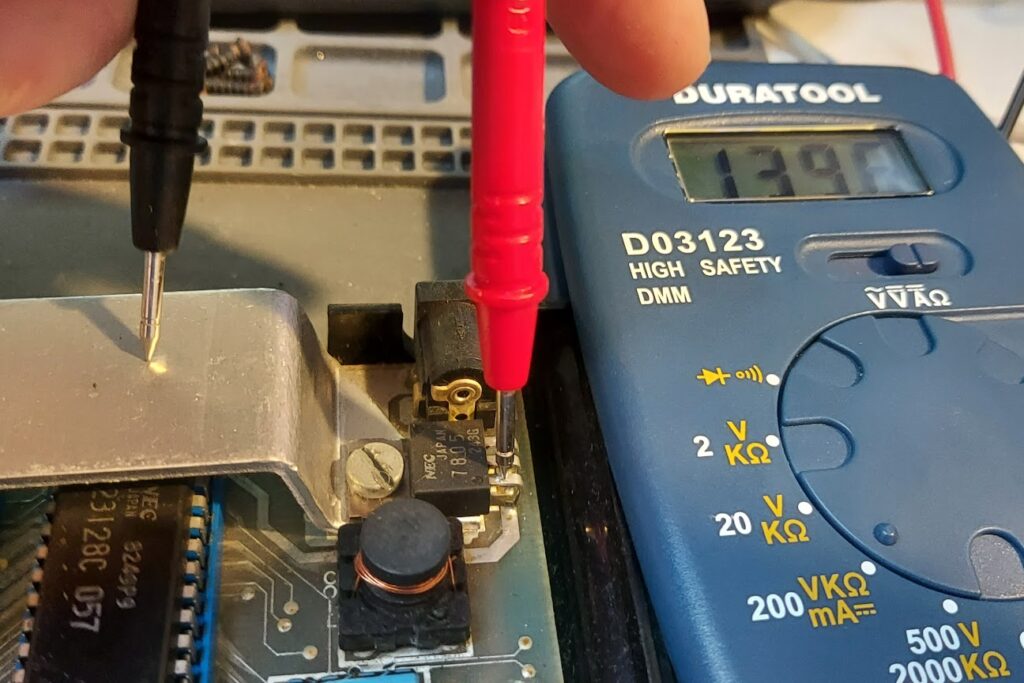
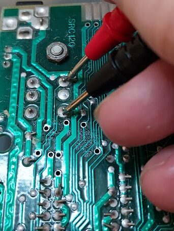
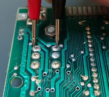
Voltage regulator
Turn multimeter to 200K Ohms
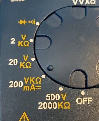
Put the black probe on the ground
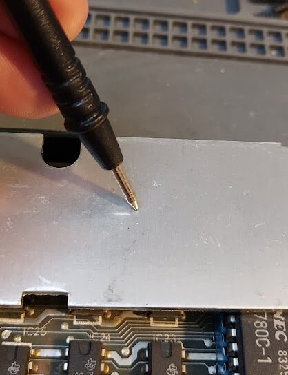
Place the red probe onto the left pin of the voltage regulator. This should over a few seconds build up to over 100.
If it is less than 100 then you have a faulty regulator and should be replaced. You can get modern replacements that improve heat from the Spectrum and allow you to remove the heatsink completely from here – RetroRevival.
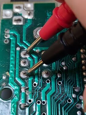
Lower RAM
Turn multimeter to 2K Ohms and put the black probe on the ground and on the lower ram chip at the bottom left check the following pins:

Pin 9: Ideally around 300 but can be 400-500. Much less suggests a problem.
Pin 16: Close to 0. Anything else suggests a broken track on the circuit board
Now change multimeter to 20K setting
Pin 8: 2.6-2.8k Ohm on an issue 3 board and above. Or 800-900 on an issue 2
Now change to 200K setting
Pin 1: Ideally between 4-500. Min of 300. Less than that suggests a problem
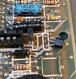
Inductor coil
Turn the board around and find the pins for the inductor coil as shown below
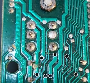
With the meter on 20K measure between the top and bottom pin on both sides of the coil. The meter should read 0
Now measure horizontally opposites
The meter should read 1 or open circuit
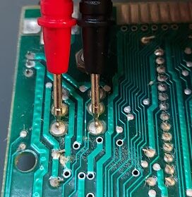
Place the multimeter in Diode test mode. The icon should look like the below
Check Diodes TR4 and TR5
TR4
For these diodes the centre leg is called “the base leg” and the ones to each side are called the “collector” and “emitter”
Hold positive (red) probe to centre (base) leg.
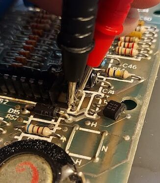
Now use the black negative probe to check the collector and emitter legs. They should both read around 0.6 to 0.9V
Replace positive probe with negative on the base leg and repeat the test with the collector and emitter legs, this should indicate an open circuit on the meter.
TR5
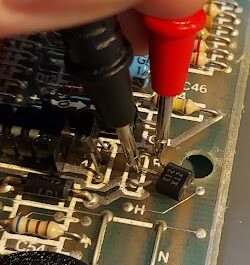
Hold negative (black) to base centre leg. Positive (red) to other legs should show 0.6 to 0.9V on collector and emitter legs. Swap to positive on base centre leg and test again to see open circuit on collector and 1.2v on emitter.