This is a copy of the recreation that used to be hosted at http://projectspeccy.com/projects/ with permission from Steve SmithThis has been a long quest for me. I’ve been searching for a SPEC-MATE for several years, since the advent of the Spectrum Next rekindled my interest in Spectrums in general. Back in the heyday of the Sinclair Spectrum and other 8-bit computers that kick started the home computing movement, I owned a Sinclair Spectrum 48K Plus that I upgraded from my original rubber key Spectrum with a kit from Sinclair. Along with my friends help, I used to hack games for infinite lives etc. This was a very common practice made easier by certian interfaces. The interfaces would freeze the game/program you were running and allow it to be saved to some sort of media, Tape, Sinclair’s own Microdrive or floppy disc for example.
Of course, these interfaces were quite expensive and above the budget of your average schoolboy hacker! I used to hack long-hand, that is to say, from the loader up. Some programs defeated my limited knowledge. Handily though, I had a friend who was into computers and had a more affluent family than I. He got a SPEC-MATE for his birthday. Later on, he loaned it to me so I could capture my game collection to Tape/Microdrive. This was a revelation! And one of the really useful features was that the SPEC-MATE made two files of main memory. This meant that you could load a dissassembler into one part of memory and a half of the programs code in the other. Hacking became exponentially easier!
Fast forward to the present day where my knowledge of hardware has come on a bit and PCB manufacture is a breeze with suppliers providing an amazingly high quality services for economic rates. I wanted to recreate a SPEC-MATE, but try as I might, I couldn’t find one to buy or loan. I hadn’t realised just how rare they had become. Then, my Facebook contact and friend Davide Barlotti offered me the loan of his. I accepted and he sent it over. This sadly coincided with a period of burnout in which I shelved the Spectrum and associated projects and left Davide’s interface safely tucked away on my shelves.
Later on, a chap by the name of Andy Lewis sent me his reverse-engineered schematic. I stored this for later use. Meanwhile, recently Davide requested I send his interface back, which I duly did and he notified me of a SPEC-MATE that had come up for sale on eBay. It was very pricey, but after searching for so long and knowing how rare they were, I snapped it up.
This fired me up into finally recreating this elusive piece of hardware. I first tested it briefly to check it worked, it did. The next step was to compare the ROM image with Davide’s. Sadly, it is the same. There was talk of an Opus Discovery compatible version of the SPEC-MATE but I believe this was never produced.
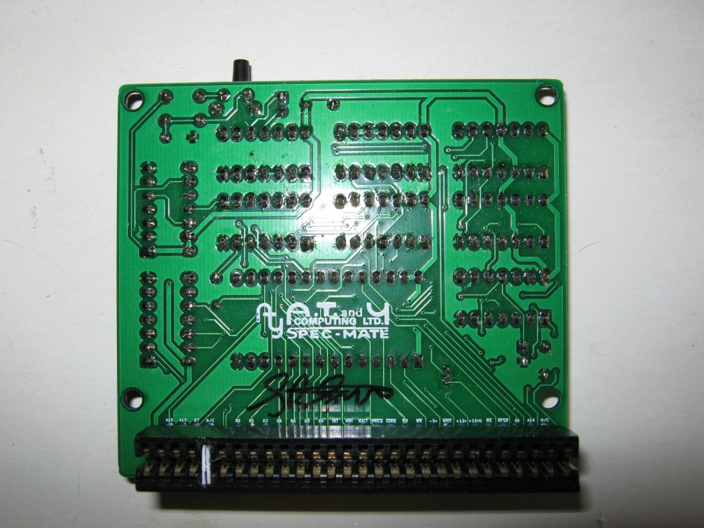
With my own device in hand, I was now confident in stripping it down to bare board in preparation to trace the circuit and verify it against Andy’s schematic. Unusually with this kind of hardware, all the ICs were socketed. I removed them and carefully placed them in a box on non-conductive sponge. I then removed all the sockets and other components with my trusty ZD-915 de-soldering gun. Lastly, removal of the edge connector and through board. Both had seen better days so I decided to replace them when I come to rebuilding it.
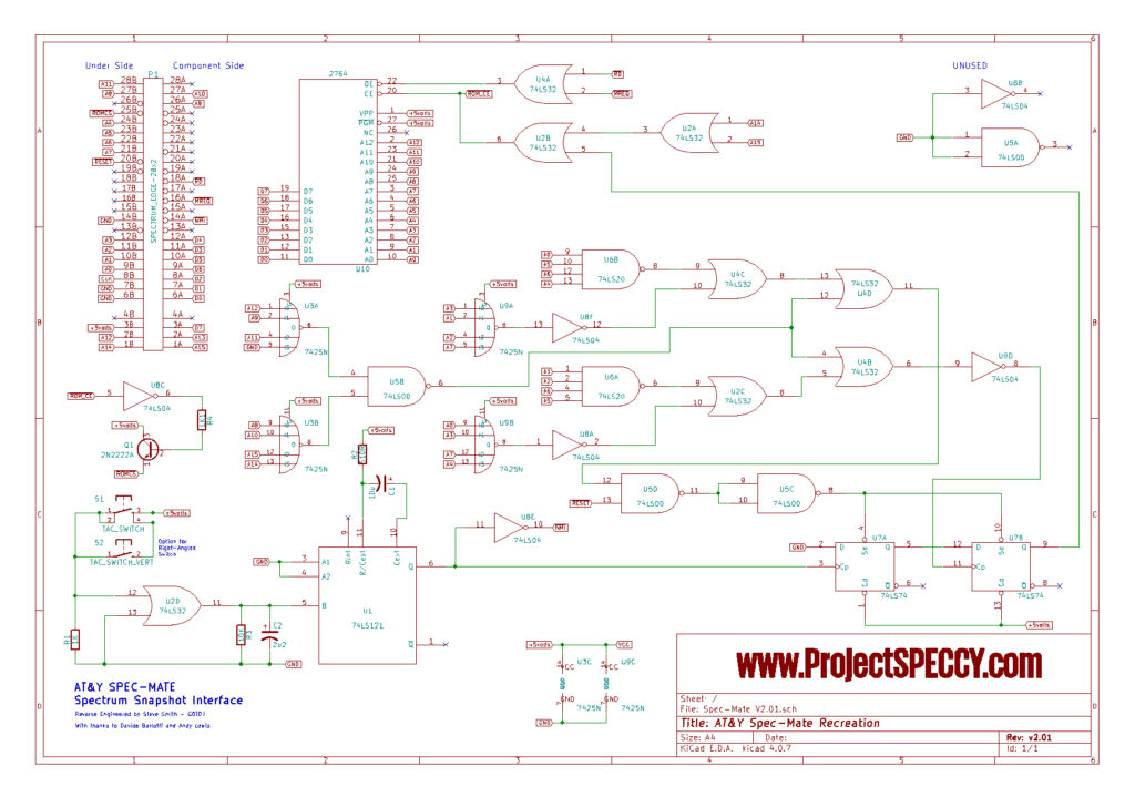
Once the board was clear, it was time to start tracing the circuit. Although I had Andy’s version, I wanted to verify it completely. I started by placing all the components on a schematic in KiCad EDA software. I then added my custom edge connector component and started to trace the connections. I started at one end of the edge connector pads and worked along, first the top row, then the bottom row. After that, I traced each connection on each IC in turn, using the boards own designations for each. Lastly, the other discreet components. This creates the schematic which I was able to match with Andy’s.
SPEC-MATE Schematic
Following on from the process of circuit tracing comes PCB design. I consciously decided not to follow the original pattern for the sake of size. Although I did start with a similar layout, I found that I could route the connections easier by repositioning various ICs. I also decided to have two trigger switches, one flat to the board and one at right-angles. The routing took several days with a number of design sessions. The result is a more compact board than the original.
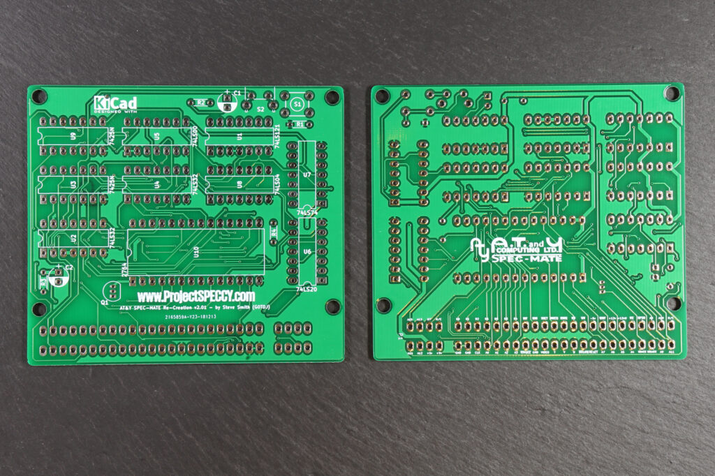
I recreated the AT&Y Logo to go on the board as an homage to the original. It is on the side facing the Spectrum along with the edge connector. JLCPCB.com fabricated the boards to their usual quality standards. Building is a simple process. I started with the IC Sockets and then added the discreets, followed by a single edge connector. I haven’t included a through board on the first build since the edge connectors I have don’t have pins that are long enough. I have ordered some long pin versions to facilitate this for the next build.
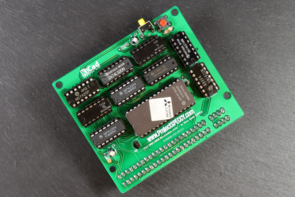
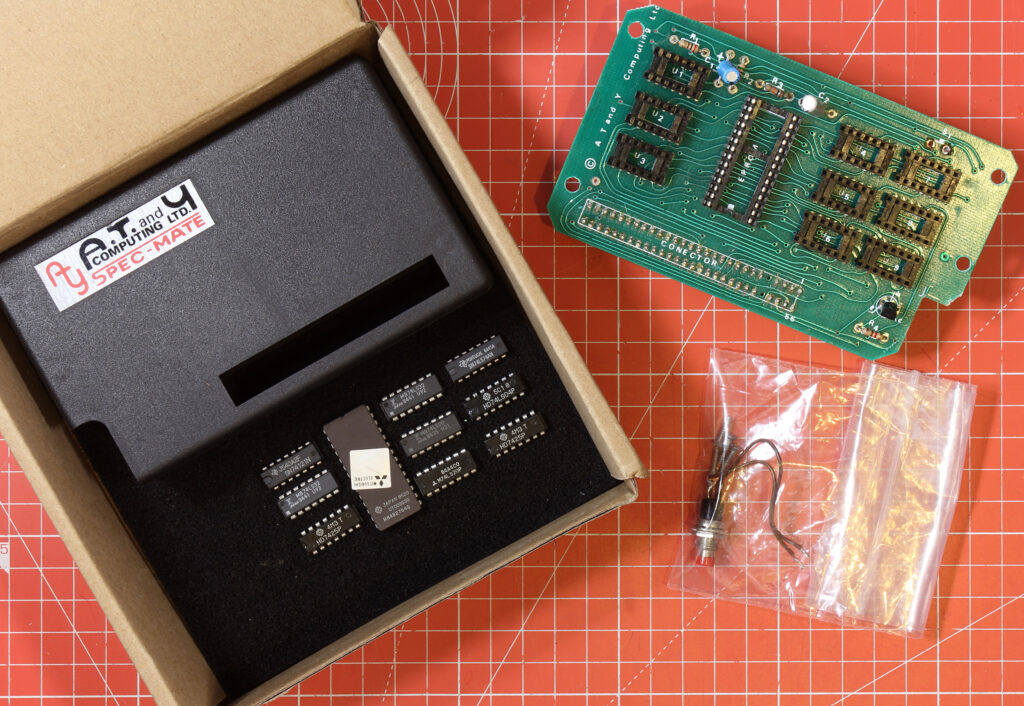
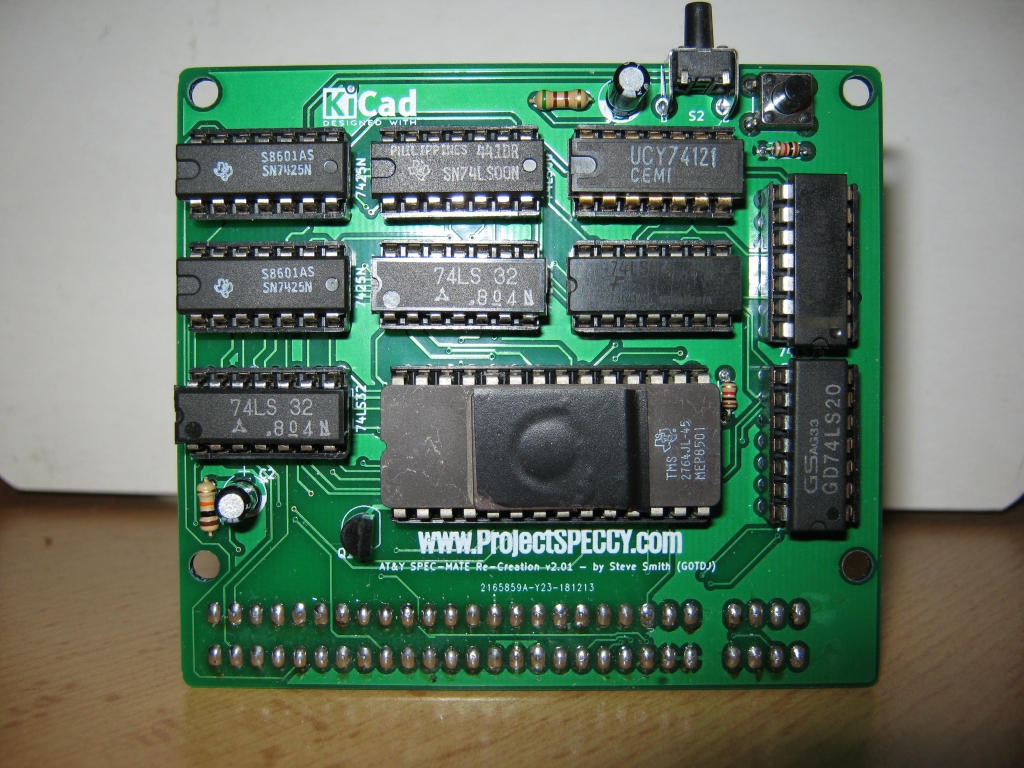
In the above image, you can see the ROM from the original interface. I later programmed my own ROM to replace it. Not having any 2764 EPROMs to hand, I used a 27C128, which is pin compatible with this board. I loaded the ROM image into the first 16k of space.
I was very pleased to find that it worked first time! I did a few basic tests saving to tape and Microdrive (using the excellent vDrive ZX). The SPEC-MATE isn’t as sophisticated as the Multiface and sometimes falls foul of Spectrum system variables, including RAMTOP. A fact I was reminded about when I tried to save a machine code program that had moved RAMTOP too low. In this instance, I set it to 65535 (With the CLEAR command). I also remembered that not all programs could be saved, depending on how it ran. Sometimes, you have to catch the program at a certain place! Oh the joys of 8-bit hacking 🙂
All the files for fabricating the Recreated SPEC-MATE PCB can be found on Github: https://github.com/lostretrotapes/AT-Y-SPEC-MATE-Re-Creation
[UPDATE 10th Feb 2019]
It seems that the interface is a little picky about what EPROM is used. I had an issue with my own build where the EPROM failed after a few uses, but it is unclear whether this was because it went out of tolerance or failed completely. Another constructor tried several EPROMs before he found one that worked satisfactorily. Investigation continues and I will publish any findings later. Suffice it to say, at the moment, you may have to try several EPROMs until you find one that works consistently.
Claudius reports Pawel’s interface is built and works well. He sent me a couple of images: