
Tools you will need
| Link | |
|---|---|
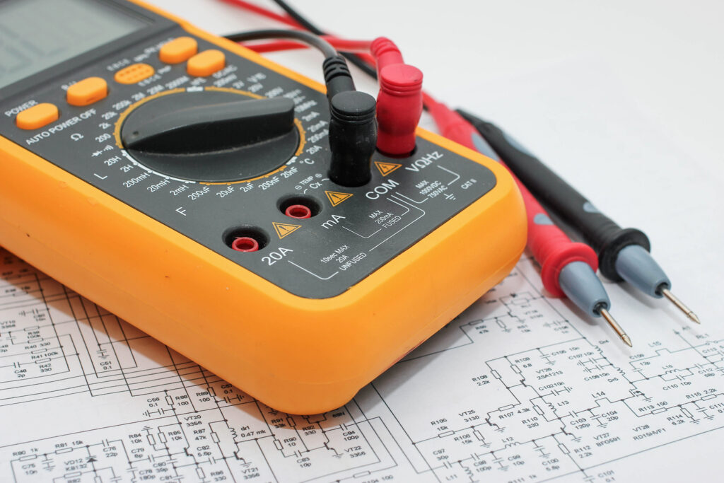
| Multimeter | https://uk.rs-online.com/web/p/multimeters/1231938 |
| 4116 Chip Tester (Optional) | https://zxrenew.co.uk/4116-Dram-checker-p225214462 https://www.ebay.co.uk/itm/124726020732 |
| Replacement 4116 (If required) | https://www.retroleum.co.uk/zx-spectrum-chips |
How To Test
Taking your Multimeter put it into DC voltage measurement mode. This can be found by looking for the following item in the select dial:
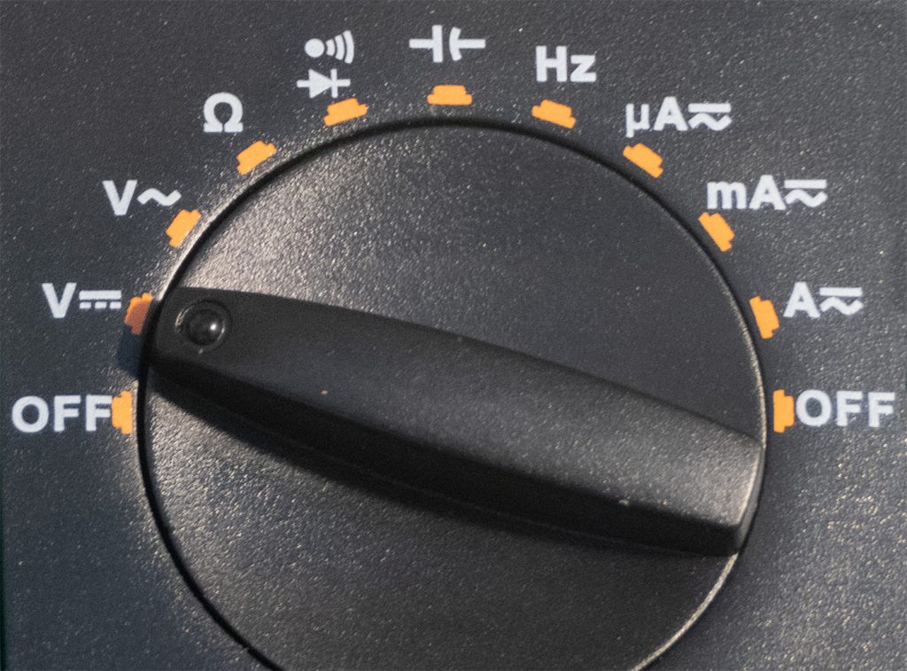
Most modern Digital Multimeters will have auto range, however if you see anything on your dials that look like 2V, 20V, 200V, 500V this means you have to manually select a range. As we are measuring up to 14V make sure you have a range selected that will give us accurate measurements in this range. You will want to look for something around 20V and select this on your dial.
Once it is selected you should see around 0 on the display, showing that you are measuring no voltage. If it is showing a value, make sure the probes aren’t touching anything, it may show a very slight voltage, this isn’t anything to worry about as long as it’s under 0.1v displaying on your meter.
Now take the black probe and press the pin against the heatsink or bare metal next to the power adapter on the ZX Spectrum, this is known as “ground” and is important to be able to measure the voltage. You can also use pin 16 on the memory chip for this, but the heatsink is better.

Now on the bottom left of the board are a row of chips labelled IC6-13. These are the lower ram 4116 chips and notorious for failing, as you might expect with a 30 year old machine. We are going to test 3 pins on these: 1, 8 and 9. To work out the PIN number you start at the top left of the chip, work down, then when you reach the bottom the numbering goes to the other side and works its way up. See the diagram below for an example.

With your black probe on the ground as described above, place the tip of the red probe on Pin 1. Your Multimeter should now read -5V. It can be above or below this by around 0.6 but any more there is likely a problem with the chip.
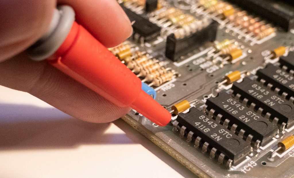
Now test the voltages to pin 8, this should read 12V and pin 9 which should read 5V.
| Pin | Voltage |
|---|---|
| 1 | -5V |
| 8 | 12V |
| 9 | 5V |
If any are low, then there is a problem. If the pin 1 is around 0v and pin 8 is between 10v and 11v this points to a problem with transistor TR4 and/or TR5 and will need to be replaced. We will cover this in a future article.
If these are all OK you can go along to the next chip to the right and take the same measurements. If you find a bad chip it is best to desolder this, and replace it. If you want to absolutely make sure that the chip is OK you will have to purchase a DRAM Tester as linked in the table at the top of this page. Desolder the chip, place it in the tester and press the test button. A green light shows the DRAM is OK, red and it’s ready for the bin.
This is also very useful for making sure that any chips you get to replace bad ones are also correct, fake and broken chips are a large problem when buying online. I have risked buying from AliExpress and it’s a bit of a lottery if you get good chips, or a load of rubbish. To be safe I recommend Retroleum from the above table link, they have always been excellent, and I highly recommend them.