
Required Tools and Materials
| Link | |
|---|---|
| Raspberry Pi Zero | https://thepihut.com/collections/raspberry-pi/products/raspberry-pi-zero-2 |
| 1GB or greater MicroSD Card | https://www.picstop.co.uk/microsd-sdhc/sandisk-industrial-microsd-class-4-uhs-1-4gb.html |
| GPIO 2×20 Female Header 2.54mm | https://www.ebay.co.uk/itm/161941307343 |
| Soldering Iron | https://pine64.com/product/pinecil-smart-mini-portable-soldering-iron/ |
| Solder | https://cpc.farnell.com/multicore-solder/3096525-m/solder-60-40-hi-act-0-5mm-250g/dp/SD00958 |
| 99.9% Isopropyl Alcohol | https://www.ebay.co.uk/itm/142697488963 |
| Philips Head Screwdriver | https://store.ifixit.co.uk/products/pro-tech-toolkit |
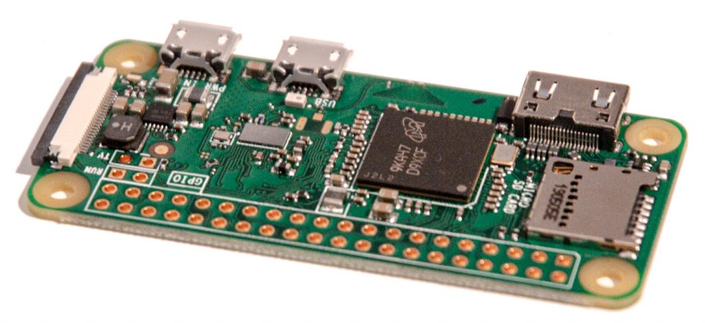
At the moment there is no point using a Raspberry Pi Zero W as the wireless can’t currently be used on the ZX Spectrum Next, so if you have one, a original non-W version is currently best used for this project.
Soldering Header onto Raspberry Pi
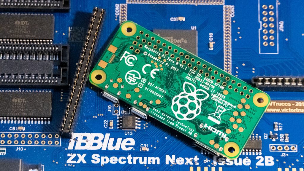
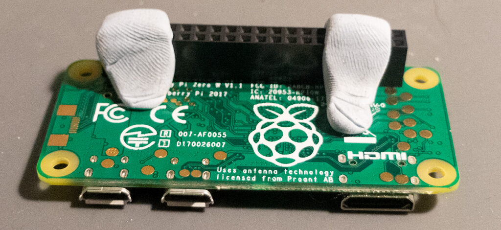
First thing to do is to solder on the header onto the Raspberry Pi. This is a relatively simple soldering job, the only real thing to look out for is to install it the correct way up, you should solder on the side where the CPU and SD card slot are on, so that the black header is on the side with the large Raspberry Pi logo. Also make sure that the header is perfectly straight up, you can do this by holding it in place with some Blu-Tak or Kapton tape and soldering the two outside corners, and then making sure it’s straight, you can then either adjust or solder the rest.
Installing Software onto the Pi Zero
To work the Pi Zero will have to have a SD card with the software to communicate with the Next installed. You can download the software here: https://zx.xalior.com/NextPi/
At the time of writing this the latest version is 0.99D. Download the .tar.gz file and extract this. If you are on Windows you will have to use a tool such as 7Zip as Windows can’t extract .gz files without a third party tool. You can download this from https://www.7-zip.org/
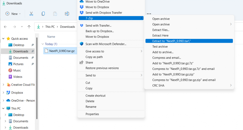
Once you extract this you will have a folder called something like NextPi_0.99D.tar. In here will be a .tar file, as you did before use 7Zip to extract this and you finally end up with a folder called NextPi_0.99D and inside you will see a .img file. This is what you use to write onto a SD card to get the Pi and Next to communicate with each other.
To write this to a SD card you can use Balena Etcher available from https://www.balena.io/etcher/
Put your SD Card in your PC memory card slot, open the application, select the .img file you just extracted and click “Flash!”
On some versions of Windows it might report after it gets to 99% validation that it has failed. This is due to Windows writing a folder to the SD card that makes it not match the original files, making validation fail. The card is fine, and will work OK, but if you want to read more about this you can refer to this StackOverflow thread: https://superuser.com/questions/1199823/how-to-prevent-creation-of-system-volume-information-folder-in-windows-10-for/1199824#1199824
You can now remove the SD card from your writer and put it in the Pi Zero.
Opening the ZX Spectrum Next Case
Flip the Next over and refer to the 6 screws illustrated in the photo below. Using a Philips head screwdriver unscrew them all and place in a safe place.
You will then be able to detach the bottom part of the case, do this and put it to one side.
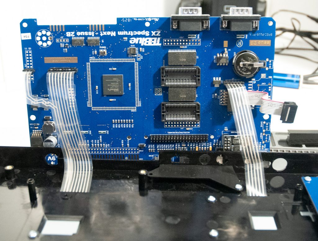
Removing the Next Board
Look for the 4 screws identified in the photo below, again using your Philips head screwdriver remove these and place safely, note that these are a lot shorter than the previous screws.
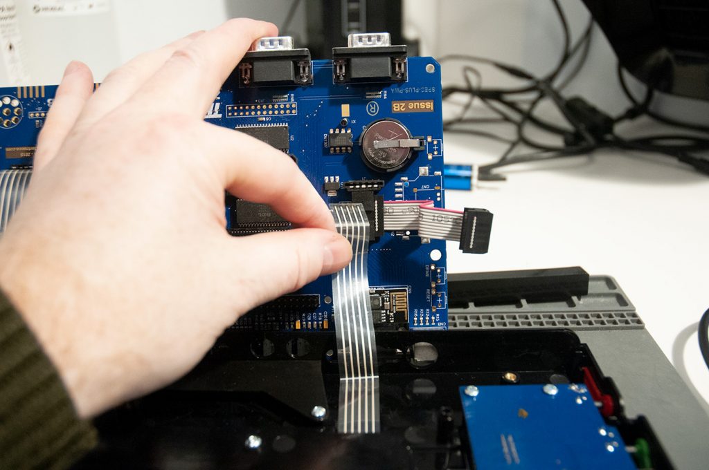
Carefully start to detach the board from the case, you will see that there is a connector on the right hand side that can be detached, as well as 3 ribbon cables that can be removed. Once you have removed these the board will come out cleanly. Place this on your desk and put the rest of the case to one side for the moment.
Installing the Pi Zero
Find the Accelerator Board pins as shown in the image below and simply place the Raspberry Pi Zero on these pins using the previously soldered header. The Pi USB and HDMI connectors should align above the HDMI and EAR/MIC connectors on the Next board as below.
Reassemble The Case
Plug the ribbon connectors back onto the PCB and replace the board as shown below. Screw the smaller of the screws back to secure it against the case. Now please the case together again and use the longer screws to join the two parts of the case together.